
Why Deterministic Timing Matters in Real-Time Simulation
A hardware-in-the-loop simulation connects mathematical models to physical controllers, sensors, actuators, data buses, and other test equipment. That connection requires the simulation to translate model variables into the signals expected by the hardware and convert hardware inputs back into values the models can use.
One way to build this connection is to embed hardware-specific details directly into the simulation model. The model might reference a particular I/O board, device channel, driver API, data format, or signal conversion.
That approach can work for a small test system, but it creates a close dependency between the model and the current test hardware. Replacing a board, moving a signal, or reusing the model on another test stand may then require changes to the model itself.
A more maintainable HIL architecture separates the simulation model from the physical I/O configuration. The model works with defined engineering variables, while an intermediate data and mapping layer connects those variables to the hardware.
How Models Become Coupled to I/O Hardware
A simulation model should primarily describe the behavior of the system being simulated. A flight-dynamics model, for example, may work with variables such as control-surface angle, airspeed, altitude, angular rate, and actuator position.
Physical hardware does not necessarily communicate using those engineering values. It may produce or consume:
- Analog voltages
- Digital states
- Pulse trains
- Raw integer values
- Encoded bus messages
- Network packets
- Device-specific status words
- Sensor or actuator signals requiring scaling
The HIL system must connect these two representations.
Tight coupling occurs when the model itself contains details such as:
- Physical board identifiers
- Channel numbers
- Driver calls
- Bus addresses
- Message-packing logic
- Raw-to-engineering-unit conversions
- Device initialization procedures
- Hardware error handling
Once those details become part of the model, the model is no longer independent of the test stand on which it runs.
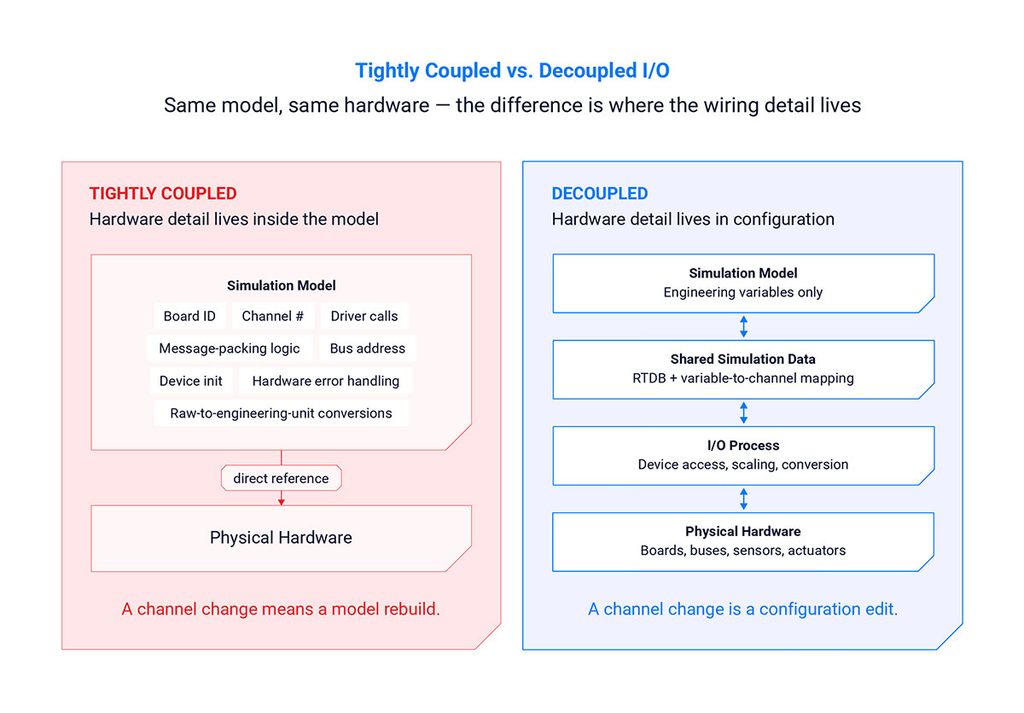
Figure 1. Tightly coupled I/O ties a model to one test stand; a decoupled architecture keeps the wiring detail in configuration instead.
The Cost of Tight Model-to-I/O Coupling
Embedding I/O configuration in a model can create problems throughout the life of a test system.
Hardware changes require model changes
An I/O board may be replaced because of obsolescence, availability, capacity, or new program requirements. If the model directly references that board, engineers may need to modify and rebuild the model even though the simulated behavior has not changed.
Models become difficult to reuse
A model developed for one laboratory may not run on another test stand with different I/O hardware. Teams can end up maintaining multiple hardware-specific versions of the same underlying model.
Responsibilities become harder to separate
Model developers may need detailed knowledge of the physical test hardware, while test engineers may need access to model source code simply to change a channel assignment.
Configuration errors become source-code changes
Moving a signal from one channel to another should normally be a configuration task. If the mapping is embedded in the model, a wiring change can require a source-code modification, rebuild, and potentially a broader review.
Hardware upgrades become more disruptive
The useful life of a simulation model may exceed the useful or supported life of an I/O device. Tight coupling makes hardware modernization more difficult because the model and the hardware must be changed together.
These issues become more significant as a test program grows across multiple laboratories, suppliers, system configurations, and years of development.
Separating Models from the I/O Configuration
A decoupled HIL architecture places an intermediary data layer between the simulation models and physical I/O.
Conceptually, the data path becomes:
Physical hardware → I/O process → shared simulation data → model
and:
Model → shared simulation data → I/O process → physical hardware
The model reads and writes named simulation variables. Dedicated I/O processes read and write the hardware. A configuration maps the model-facing variables to physical channels, messages, or devices.
Each part has a clearer responsibility.
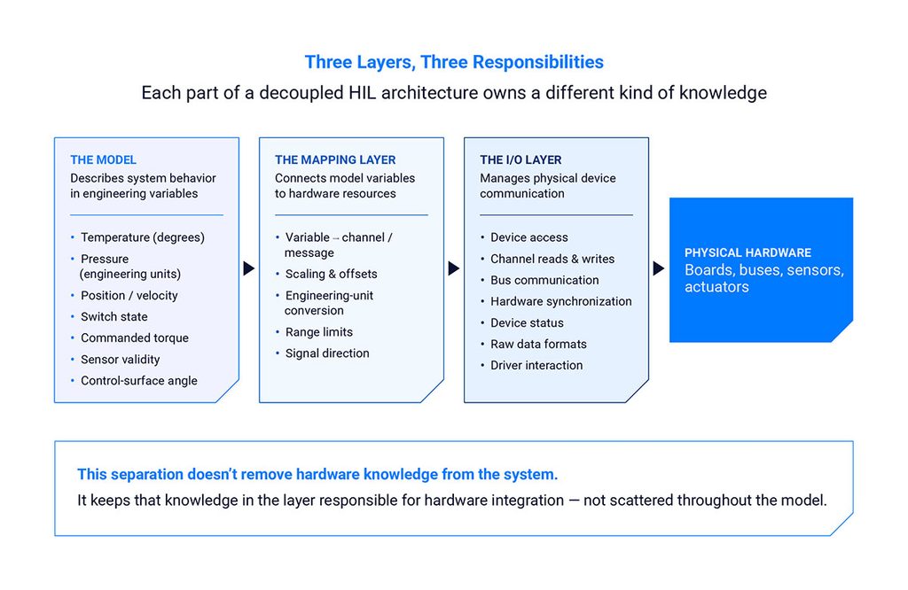
Figure 2. The model, the mapping layer, and the I/O layer each own a different kind of knowledge.
The model defines system behavior
The model works with variables that make sense for the simulated system, such as:
- Temperature in degrees
- Pressure in engineering units
- Position or velocity
- Switch state
- Commanded torque
- Sensor validity
- Control-surface angle
The I/O layer handles physical communication
The I/O process manages details such as:
- Device access
- Channel reads and writes
- Bus communication
- Hardware synchronization
- Device status
- Raw data formats
- Driver interaction
The mapping layer connects the two
The configuration defines how a model variable corresponds to a hardware resource. It may also describe scaling, offsets, engineering units, range limits, or signal direction.
This separation does not eliminate the need to understand the hardware. It keeps hardware-specific knowledge in the part of the system responsible for hardware integration.
A Simple Model-to-I/O Mapping Example
Suppose a flight-control model produces an elevator-position variable in degrees. The connected controller expects that position to be represented as an analog voltage.
With tightly coupled code, the model may calculate the voltage and write it directly to a particular analog-output channel.
With a separated architecture:
- The model writes the elevator position in degrees to a named simulation variable.
- The I/O configuration maps that variable to an analog-output channel.
- The mapping applies the required conversion between degrees and volts.
- The I/O process writes the converted value to the physical device.
If the signal is later moved to another channel, the mapping can be changed without altering the flight-dynamics calculations.
If a replacement I/O device uses a different driver, the I/O process or device configuration may need to change. The model can remain unchanged as long as its variable interface and expected behavior remain valid.
Benefits Across the Test Lifecycle
Reuse models across test environments
A model that uses a defined data interface can be deployed across multiple test stands with different I/O configurations. Each environment supplies the mappings needed to connect the same model variables to its hardware.
This can also support progression through different development stages. A model may first run without physical I/O for functional testing and later be connected to a controller in a hardware-in-the-loop environment.
Modify signal assignments without rebuilding the model
Channel assignments, signal scaling, and some hardware configurations can be managed separately from the model source. This reduces unnecessary model changes when the simulated behavior has not changed.
Support parallel development
Model developers can work against an agreed variable interface while test engineers configure hardware mappings. The teams do not need to wait for every physical channel assignment to be finalized before model integration begins.
Accommodate hardware obsolescence
Long-running aerospace, defense, automotive, energy, and industrial programs may replace test hardware several times. Separating the model from the I/O layer limits how far those hardware changes propagate through the simulation environment.
Integrate models from multiple sources
Models may come from different internal teams, suppliers, commercial modeling tools, or custom codebases. A shared data interface provides a common integration point without requiring every model to implement every device API.
Make configuration easier to review
When mappings are stored as configuration rather than scattered through model code, engineers can review which variables connect to which channels. Configuration files can also be controlled alongside other test assets.
Separation Does Not Eliminate Integration Work
Model and I/O independence should not be interpreted as complete insulation from hardware behavior.
The test still needs to account for:
- Signal ranges and units
- Quantization
- Saturation
- Sensor and actuator behavior
- Bus update rates
- Transport delays
- Device initialization
- Invalid or missing data
- Electrical characteristics
- Fault-injection requirements
- Synchronous and asynchronous communication
Changing an I/O device may also change its timing behavior, resolution, or supported functions. Those changes require integration testing even if the model source does not need to be modified.
A separated architecture reduces unnecessary coupling. It does not remove the responsibility to verify the complete model, mapping, I/O, and hardware configuration.
Timing Still Matters
An intermediary data layer must support the timing requirements of the simulation.
For synchronous I/O, input values need to be available before the corresponding model calculations begin. Model outputs must then reach the hardware at the intended point in the simulation cycle.
Asynchronous devices require a controlled method for updating shared data without unexpectedly disrupting time-critical execution. The test architecture must define when asynchronous values become visible to the models and how older or missing data is handled.
As explained in Why Deterministic Timing Matters in Real-Time Simulation, numerically correct values can still produce misleading test behavior if they arrive at the wrong time.
A later article in this series will examine synchronous and asynchronous I/O in more detail.
Configuration Management Becomes Part of Test Management
Separating mappings from models makes the I/O configuration easier to change, but those changes must still be controlled.
A complete test definition may need to identify:
- The model versions
- The I/O configuration
- Variable-to-channel mappings
- Scaling and conversion settings
- Initial conditions
- Test scripts
- Scheduler configuration
- Data-logging selections
- Hardware and driver versions
Recording only the model version is not enough to reproduce a HIL test. Two runs using the same model can behave differently if their mappings, units, channel assignments, or I/O timing differ.
Teams should treat the I/O configuration as a versioned test asset and include it in review, release, and change-control processes.

Figure 3. A reproducible HIL test definition records more than the model version mappings, scaling, scripts, and configuration all belong in the same versioned bundle.
Model and I/O Independence in SIMulation Workbench
SIMulation Workbench uses a memory-resident real-time database, or RTDB, as the shared data layer among simulation models, I/O tasks, scripts, and other test processes.
The RTDB contains the data items used by the simulation and defines how model variables connect to I/O resources. Models interact with those data items rather than directly managing each physical device.
I/O tasks operate as independent processes responsible for reading from or writing to supported hardware. Depending on the device and test requirements, those tasks can operate synchronously within the simulation loop or asynchronously outside it.
This architecture allows models and I/O configurations to be managed separately. A channel assignment or supported hardware configuration can be changed without modifying the underlying model, provided the model’s variable interface and required behavior remain the same.
The same shared data architecture also allows scripts, logging tools, and visualization applications to access selected simulation values without embedding those functions into the model.
Questions to Ask When Evaluating HIL I/O Architecture
Engineering teams evaluating a simulation platform should ask:
- Do models call device drivers directly?
- Are physical channel identifiers embedded in model code?
- Can I/O mappings be changed without rebuilding the model?
- Where are raw-to-engineering-unit conversions performed?
- Can the same model be reused with different I/O configurations?
- How are data items named and defined?
- How are synchronous and asynchronous devices handled?
- Can custom hardware be integrated through a defined I/O interface?
- Are configuration changes traceable and version-controllable?
- How are mappings included in a repeatable test definition?
- What testing is required after an I/O device is replaced?
- Can multiple models exchange data through the same integration layer?
These questions help determine whether the architecture can adapt as the test system changes.
Conclusion
Simulation models and test hardware often have very different lifecycles. Models evolve as system requirements change, while I/O devices change because of capacity, availability, technology updates, or obsolescence.
Embedding physical I/O details directly into a model ties those lifecycles together. Even a minor channel or device change can then require model modification, rebuilding, and additional review.
Separating the model from the I/O configuration creates a cleaner boundary. Models describe system behavior, I/O processes manage physical devices, and a controlled mapping layer connects the two.
The result is not a hardware-independent test with no integration effort. It is an architecture in which hardware changes, model changes, and configuration changes can be managed more deliberately.
For a broader discussion of model integration, deterministic scheduling, multicore execution, and test automation, download Designing Scalable, Deterministic X-in-the-Loop Simulation Environments.
Frequently Asked Questions
What is I/O mapping in HIL simulation?
I/O mapping defines how simulation variables connect to physical hardware resources such as analog channels, digital channels, communication-bus messages, or network interfaces. It may also define signal direction, scaling, offsets, and engineering-unit conversions.
Does model and I/O separation mean a model never changes when hardware changes?
No. A model can remain unchanged when the hardware change preserves the same variable interface and simulated behavior. Changes that affect timing, resolution, range, dynamics, or functional requirements may still require model or interface updates.
Why use a real-time database in a simulation system?
A real-time database can provide a shared, structured data layer between models, I/O processes, scripts, logging tools, and visualization applications. This reduces the need for each model to communicate directly with every hardware device.
Does an intermediary data layer add latency?
Every data exchange has some processing cost. The architecture must be designed and measured to ensure that synchronous data transfers complete within the simulation deadline. A memory-resident implementation can avoid slower storage-based or loosely coordinated exchanges, but the complete timing path still needs verification.
Can the same model be used for software-in-the-loop and hardware-in-the-loop testing?
Potentially. If the model uses a stable data interface rather than direct hardware calls, different configurations can connect it to simulated inputs during software-in-the-loop testing and physical I/O during HIL testing. Differences between the environments still need to be understood and validated.
Should I/O configuration files be version-controlled?
Yes. Channel mappings, signal conversions, device settings, and related configuration can materially affect test behavior. They should be managed as part of the repeatable test definition.
Related Articles
-

White Paper: From Subsystem to Preflight A Progressive Hardware-in-the-Loop Validation Framework for Missile Development
White Paper: From Subsystem to Preflight A Progressive Hardware-in-the-Loop Validation Framework for Missile Development Discover a practical, three-stage approach to identifying subsystem, closed-loop, and mission-level integration risks before committing to flight testing.…
-

U.S. Treasury Assistant Secretary Chris Pilkerton Visits CCRT
Assistant Secretary Chris Pilkerton Visits Concurrent Real-Time Concurrent Real-Time was honored to welcome Chris Pilkerton, Assistant Secretary of the Treasury for Investment Security and Chair of the Committee on Foreign Investment in…
-

Real-Time Simulation for Aerospace and Defense: An Engineering Guide
Real-Time Simulation for Aerospace and Defense: An Engineering Guide Real-time simulation allows aerospace and defense teams to execute system models in synchronization with actual elapsed time. Unlike offline simulation, a real-time environment…