
Synchronous vs. Asynchronous I/O in Real-Time Simulation
A real-time simulation must exchange data with physical devices while continuing to execute its models on schedule. Some of those data exchanges need to occur at a precise point during every simulation cycle. Others are initiated by devices that operate according to their own timing.
These two situations are generally handled through synchronous and asynchronous I/O.
The distinction affects more than how data is received. It determines where an I/O operation executes, how it interacts with the simulation loop, when new values become visible to models, and what happens if a device is slower than expected.
Neither approach is inherently better. A practical hardware-in-the-loop system often uses both.
How I/O Fits into a Real-Time Simulation Cycle
A simplified synchronous simulation cycle contains three primary stages:
- Read the inputs required for the current cycle.
- Execute the scheduled simulation models.
- Write the calculated outputs to the connected hardware.
The complete cycle must finish before the next simulation period begins.
If the simulation period is one millisecond, all synchronous input processing, model calculations, output processing, and required scheduler activity must fit within that millisecond.
Not every connected device can or should participate directly in this loop. A fast analog input may need to be sampled at the start of every cycle, while a serial interface may deliver messages irregularly and independently of the simulation schedule.
The architecture must place each operation where it can meet its functional requirements without unnecessarily interfering with time-critical execution.
What Is Synchronous I/O?
Synchronous I/O is coordinated directly with the real-time simulation loop. The simulation controls when the I/O task runs, and the operation occurs at a defined point in the cycle.
A common sequence is:
- Synchronous input tasks acquire hardware values.
- The values become available to the simulation models.
- The models calculate their next state.
- Synchronous output tasks write the calculated results to the hardware.
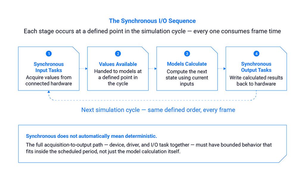
Figure 1. The synchronous I/O sequence — each stage occurs at a defined point in the cycle and consumes frame time.
This creates a clear timing relationship between the hardware signals and the model execution.
Synchronous I/O is commonly used when a signal must be sampled or generated at the simulation rate. Depending on the system, examples may include:
- Analog inputs and outputs
- Digital inputs and outputs
- Synchro and resolver interfaces
- Pulse or waveform generation
- Encoder simulation
- Selected relay or discrete interfaces
- FPGA-based signal processing
The device, driver, and I/O task must all be capable of operating within the simulation’s timing budget.
Advantages of Synchronous I/O
Defined timing relative to the model
Engineers know when an input was acquired and when the corresponding output was generated relative to the model calculation.
This is important in closed-loop tests where even a small unintended delay can change how the controller experiences the simulated system.
Consistent signal updates
If an input is scheduled every simulation cycle, the model receives a regularly updated value rather than depending on an independently timed device event.
Easier cycle-by-cycle analysis
The relationship among input acquisition, model execution, and output generation is easier to reconstruct because each operation belongs to a defined simulation frame.
Direct support for fast control loops
Signals that must track the base simulation rate can be processed as part of the same scheduled loop as the models that consume or produce them.
Constraints of Synchronous I/O
The predictability of synchronous I/O comes with strict timing requirements.
Every operation consumes frame time
Time spent reading or writing hardware reduces the time available for model calculations and other synchronous work.
The device must respond predictably
A device that occasionally takes longer than expected can delay the complete simulation cycle. The same concern applies to its driver and I/O-processing code.
Blocking operations can cause overruns
A synchronous task should not wait indefinitely for data or hardware availability. Blocking behavior inside the simulation loop can prevent the remaining models and output tasks from running on time.
Increasing the number of channels can change the timing budget
An I/O task that meets its deadline with a small channel count may take longer as more signals are added. Engineers should test the complete intended configuration rather than assuming performance from a minimal setup.
Synchronous does not automatically mean deterministic. The entire acquisition and output path must have bounded behavior that fits within the scheduled period.
What Is Asynchronous I/O?
Asynchronous I/O operates independently of the main simulation loop. The device or communication interface may generate or receive data according to its own timing rather than once per simulation frame.
Examples can include:
- Serial communications
- Network messages
- ARINC 429
- AFDX
- MIL-STD-1553
- Device status updates
- Operator-interface events
- External systems running at unrelated rates
Whether a specific interface should be synchronous or asynchronous depends on the device, driver, test requirements, and platform implementation. The communication standard alone does not always determine the correct architecture.
An asynchronous task typically receives or transmits data outside the time-critical loop. New input data is then transferred to the simulation through a controlled handoff mechanism.
Advantages of Asynchronous I/O
The simulation loop does not wait for an irregular device
A serial or network device may not provide data during every simulation cycle. Processing it asynchronously prevents the time-critical loop from blocking while waiting for a message.
Independently timed interfaces can operate naturally
Some buses and devices already control their own update schedules. They do not need to be forced artificially into the simulation’s base rate.
Slow support functions remain outside the critical path
Status messages, operator commands, configuration traffic, and similar activity can be processed without consuming time in every model cycle.
Communication workloads can be isolated
Asynchronous processing can run on a different thread or processor core, reducing direct contention with scheduled simulation models.
Challenges of Asynchronous I/O
Moving an operation outside the simulation loop does not eliminate timing concerns. It changes the questions engineers need to answer.
When does new data become visible?
A message may arrive while a model is executing. The architecture must define when that value becomes available for use—immediately, at the next input phase, or at another controlled update point.
How old is the data?
A model may continue using the last received value between asynchronous updates. The system should identify when the value becomes stale and determine how the test should respond.
What happens when messages arrive faster than they can be processed?
The interface may need buffering, queue limits, overflow handling, or a defined policy for replacing older values with newer ones.
How are missing messages handled?
The simulation may hold the previous value, apply a default, mark the signal invalid, trigger a fault, or stop the test. That decision should be explicit.
How are asynchronous events correlated with simulation time?
Timestamps may be needed to determine when an event occurred relative to the simulation’s scheduled cycles.
These issues are especially important when asynchronous data affects a time-critical model or fault-injection sequence.
Synchronous and Asynchronous I/O Compared
| Consideration | Synchronous I/O | Asynchronous I/O |
| Execution timing | Controlled by the simulation loop | Controlled separately or by the device |
| Typical update pattern | Once per cycle or at a scheduled rate | Irregular or independently scheduled |
| Relationship to model execution | Occurs at a defined point before or after models | Data is handed into or out of the simulation at a controlled boundary |
| Effect on frame budget | Directly consumes simulation-cycle time | Primarily processed outside the critical loop |
| Main risk | Delaying or overrunning the simulation cycle | Stale, queued, missing, or inconsistently applied data |
| Common use | Fast physical signals and closed-loop interfaces | Communication buses, networks, serial devices, and support traffic |
| Required controls | Bounded execution time and nonblocking behavior | Buffering, timestamps, data-age rules, and controlled updates |
The table describes general patterns rather than fixed rules. A particular interface may support more than one operating method.

Figure 2. Synchronous and asynchronous I/O trade predictable timing for independence from the simulation loop.
Choosing the Appropriate I/O Method
The correct choice depends on how the signal affects the simulation.
Questions to consider include:
- Must the signal update during every simulation cycle?
- Does the device produce data on demand or on its own schedule?
- Can its maximum response time fit within the frame?
- Will the model remain valid if the value is held between updates?
- Is the exact arrival time important?
- Can messages arrive in bursts?
- What should happen if data is late or missing?
- Does the device driver ever block?
- Is a timestamp required?
- How much processing is required to decode the data?
- Can the I/O task run on a separate processor core?
- Does the interface participate in a closed-loop control path?
The choice should be based on timing and data-flow requirements rather than convenience alone.
Managing Asynchronous Data Safely
A controlled boundary between asynchronous activity and the simulation loop helps preserve data consistency.
Instead of allowing an asynchronous task to alter model-facing data at an arbitrary point during execution, the system can:
- Receive the device data outside the loop.
- Place the update in a buffer or queue.
- Transfer the value into the shared simulation data at a defined point.
- Allow the models to consume the new value during a subsequent cycle.
This prevents a model from reading a partially updated data structure or receiving different portions of the same message at different points in its calculation.
The design should also define:
- Buffer size
- Queue-overflow behavior
- Whether every message must be preserved
- Whether only the latest value matters
- Data-validity indicators
- Timeouts
- Timestamp handling
- The relationship between device time and simulation time
An asynchronous interface can coexist with deterministic model execution when the transfer boundary and failure behavior are controlled.
Mixing Synchronous and Asynchronous I/O
A single HIL test may contain both types of I/O.
For example, a flight-control test might use:
- Synchronous analog and digital signals for control surfaces
- Synchronous sensor simulation for high-rate feedback
- Asynchronous ARINC messages for avionics data
- Asynchronous Ethernet traffic for configuration or monitoring
- Operator commands arriving independently from a control station
The key is to define how information moves between these paths.

Figure 3. A single HIL test can mix both fast signals stay inside the loop, irregular traffic crosses in at a controlled boundary.
An asynchronous command that changes the behavior of a synchronous model should normally become active at a controlled simulation boundary. Similarly, data produced in the synchronous loop may be copied to an asynchronous communication task after the critical calculations are complete.
This keeps slower or irregular communication from taking control of the real-time schedule.
Relationship to Model and I/O Independence
Separating simulation models from physical device code makes it easier to assign the appropriate execution method to each interface.
As discussed in Why HIL Simulation Models Should Be Independent of the I/O Configuration, models can work with defined engineering variables while dedicated I/O tasks manage device communication.
The model does not need to know whether a value came from an analog channel, a bus message, or another simulation process. The I/O and mapping configuration determines how that value enters the shared simulation environment and when it becomes available.
This separation also makes it possible to change an interface implementation without embedding its scheduling and driver logic throughout the models.
Synchronous and Asynchronous I/O in SIMulation Workbench
SIMulation Workbench uses independent I/O tasks to connect physical devices with its memory-resident real-time database.
For synchronous I/O, input tasks run within the simulation loop before the model-execution portion of the cycle. Synchronous output tasks run after the models have calculated their outputs. This establishes a defined input-model-output sequence.
Asynchronous I/O tasks operate outside the simulation loop. Rather than changing the real-time database at an arbitrary point, asynchronous input updates are passed through a controlled queue and applied during the simulation’s input-processing phase.
This allows independently timed devices to exchange data with the simulation while keeping the model-facing update point coordinated with the scheduled loop.
The appropriate configuration depends on the supported device, the required signal behavior, and the timing requirements of the test.
Testing the Complete I/O Configuration
I/O timing should be evaluated with the complete test configuration operating.
That includes:
- All expected models
- The intended channel count
- Representative bus traffic
- Data logging
- Test scripts
- Visualization clients
- Network activity
- Fault-injection scenarios
- Peak message rates
- Missing or delayed data conditions
A test that works with one device and a small number of signals may behave differently when the full workload is introduced.
Engineers should monitor synchronous execution time, asynchronous queue behavior, data age, dropped messages, timeouts, and simulation overruns. As explained in Why Deterministic Timing Matters in Real-Time Simulation, the relevant measurement is the timing behavior of the complete system—not just an isolated model or device.
Conclusion
Synchronous and asynchronous I/O serve different purposes in a real-time simulation.
Synchronous I/O provides a defined timing relationship between physical signals and model execution, but every operation must fit within the simulation period. Asynchronous I/O accommodates devices that operate independently, but it requires explicit handling of data age, buffering, update timing, and missing messages.
A robust HIL architecture does not force every device into the same execution model. It identifies which signals belong inside the time-critical loop, which can operate outside it, and how data moves safely between the two.
For a broader discussion of I/O architecture, model separation, scheduling, multicore execution, and test automation, download Designing Scalable, Deterministic X-in-the-Loop Simulation Environments.
Frequently Asked Questions
What is synchronous I/O in real-time simulation?
Synchronous I/O executes at a defined point in the real-time simulation loop. Inputs are typically acquired before model execution, and outputs are written after the models calculate their results.
What is asynchronous I/O in real-time simulation?
Asynchronous I/O operates independently of the main simulation loop. Data is received or transmitted according to a separate schedule and transferred to the simulation through a controlled update mechanism.
Is synchronous I/O always more deterministic?
No. A synchronous task can disrupt deterministic execution if its device or driver blocks or has unbounded response time. Its maximum execution time must fit within the simulation-cycle budget.
Can asynchronous I/O be used in a deterministic simulation?
Yes. Asynchronous processing can operate outside the critical loop while transferring data at controlled simulation boundaries. The system must define buffering, data age, update timing, and error behavior.
How should a simulation handle stale asynchronous data?
The test definition should specify a data-age limit and a response. Possible responses include holding the previous value, marking it invalid, applying a default, triggering a fault, or stopping the test.
Can the same communication interface be either synchronous or asynchronous?
Potentially. The correct method depends on the hardware, driver, update behavior, platform capabilities, and test requirements, not only the name of the communication standard.
Related Articles
-

White Paper: From Subsystem to Preflight A Progressive Hardware-in-the-Loop Validation Framework for Missile Development
White Paper: From Subsystem to Preflight A Progressive Hardware-in-the-Loop Validation Framework for Missile Development Discover a practical, three-stage approach to identifying subsystem, closed-loop, and mission-level integration risks before committing to flight testing.…
-

U.S. Treasury Assistant Secretary Chris Pilkerton Visits CCRT
Assistant Secretary Chris Pilkerton Visits Concurrent Real-Time Concurrent Real-Time was honored to welcome Chris Pilkerton, Assistant Secretary of the Treasury for Investment Security and Chair of the Committee on Foreign Investment in…
-

Real-Time Simulation for Aerospace and Defense: An Engineering Guide
Real-Time Simulation for Aerospace and Defense: An Engineering Guide Real-time simulation allows aerospace and defense teams to execute system models in synchronization with actual elapsed time. Unlike offline simulation, a real-time environment…